 |
Computer Graphic Rendering of Material Surfaces |
 |
|
Computer Graphic Rendering of Material Surfaces |
|
Rendered Images using NIST Data
iBRDF was used to render reflectance data coming from samples of black glass covered with a layer of clear epoxy. We were interested in seeing how well the rendered images showed the gloss variations in the samples. The reflectance modeling used for these samples makes use of surface topographical measurements - an approach that is new in the rendering field. Local surface height variations - measured using a scanning white light interferometer - were used to determine surface normals needed to compute the scattering direction. The BRDF was then computed by simulating the uniform illumination of the surface for various incident directions, and counting the number of scattered rays that reach detectors distributed over a hemisphere of directions. Details on sample preparation, reflectance modeling, and measurement can be found in McKnight et al. [MCKNI01]. Figure 13 shows two black glass tiles modelled with the generated BRDF. The tile on the left has rms roughness 201nm while the tile on the right is 805nm. The images were consistent with visual inspection of the tiles. The study demonstrated that gloss loss due to surface roughening could in fact be predicted by the rendering. This work is reported in Hunt et al. [HUNT01].
Figure 13: Rendering from reflectance data generated using the Ray method and a surface topographical map of coated epoxy samples with rms roughness values 201 nm (left) and 805 nm (right).
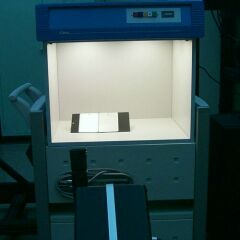
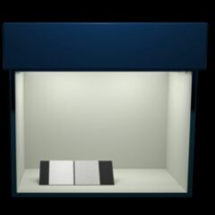
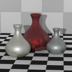
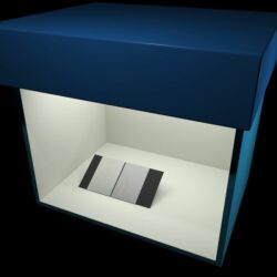
BRDF data obtained using the NEFDS measurement protocol - as discussed in NIST Data - was used to render images of surfaces composed of fine and coarse metallic flakes. The difference in the reflection properties of the two metallic surfaces can be seen in the rendered image of Figure 14. Figure 15 (left) contains a photograph of the same two surfaces placed in a light booth. To the right of the photograph is a rendering of the two surfaces using the modelled BRDF.
Figure 14: Coarse and fine metallic paint on vases
Figure 15: (left) Photograph of two samples dominated by fine and coarse metallic flake set in a light booth. (right) Rendered image of the same light booth and samples.
|
Privacy Statement/Security Notice | Disclaimer | FOIA NIST is an agency of the U.S. Commerce Department's Technology Administration.
|