Michael J. Donahue: Magnetic Force Microscopy
Magnetic force microscopy (MFM) is an extension of atomic force microscopy (AFM) that images magnetization patterns with sub-micron resolution. (AFM is itself an outgrowth of STM---scanning tunneling microscopy.) The instrument we use operates in a two pass fashion, as illustrated in the following schematic (all distances are approximate):
The first pass is a standard AFM trace that maps out the surface topography by gently tapping the tip along the surface. A second pass then samples the magnetic stray field by scanning at constant height above the surface. The tip is coated with a magnetized material (e.g., CoCr or NiFe), so changes in the magnetic field affect the resonance characteristics of the cantilever, which are detected by the laser/photo-detector setup.
Below is an MFM/AFM image of an electro-deposited Ni film on Cu (100).
The left hand image is of the magnetic stray field, the right is the
surface topography. The Ni film has a nominal thickness of 400 nm,
but we observe a hole left by a gas bubble during the deposition
process:
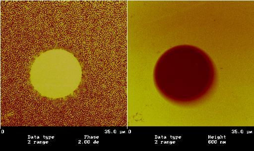
The dark (light) stripes in the left hand image indicate domains with
a relatively upward (downward) magnetization component. Notice that
the width of the domains decreases at the hole edge. This is
caused by the narrowing of the nickel film at the lip of the hole; Our
studies with samples of various thicknesses show that the domain
width is proportional to the square root of the film thickness.
The light color of the middle of the hole in the magnetic image would seem to indicate the presence of a strong field emanating from the bare Cu substrate. This can be checked by reversing the magnetization of the tip and rescanning. True magnetic features will switch colors (light to dark and dark to light), but the above hole doesn't switch. Actually, the proper interpretation is that the rest of the image stays dark, indicating that the tip is partially magnetizing the Ni film.
One final note: The apparent asymmetry in the right hand topographic image is due primarily to scan direction and tip shape effects.
The next series shows a magneto-optical indicator film (MOIF) image
(left) and two MFM images of a granular AgCo film.
These pictures indicate the complementary nature of the two
techniques. MOIF allows one to easily image large scale magnetic
structures, while MFM can reveal fine details about those structures.
Date created: May 18, 2004 | Last updated: May 18, 2004 Contact: Webmaster