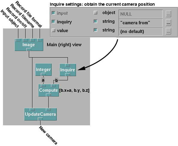
Starting with a network that displays a view of a 3D visualization, it is a straightforward matter to create a sequence of image frame pairs to be viewed with stereo display apparatus such as the Crystal Eyes stereo viewing system.
The basic idea is to take the original camera and use it to create a new camera shifted slightly to the left. It is important to keep the new (left) camera pointed at the same 'to' location.
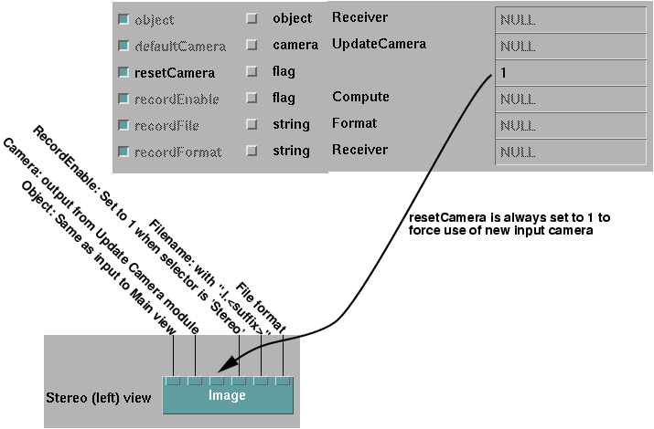
This new camera is then used as the default camera for a new Image module.
The Image module will create the output image files. Displaying the left view is necessary
due to the way DX saves images. The image to be saved MUST be displayed
on the screen. If there is an overlapping window in front of the image
window, the portion that overlaps will also be stored in the output file.
It is important to keep the image window in front of all other windows.
The particles are elliptical and vary in size. Their initial positions are randomly determined. The motion of the particle, position and attitude, are determined by the simulation model. A rectangular fin structure has been added to each particle in the visualization to make it easier to discern the attitude of the particle. This is not present in the simulation and has no effect on the motion of the particles.
We had added the ability to write frames to individual image files in
a previous version of the visualization. Now we will add another camera
to produce a second image for stereo viewing.


This image module will also save the left view images to files, so we
have to implement a method for systematically managing the filenames, file
types and the Record Enable flag.

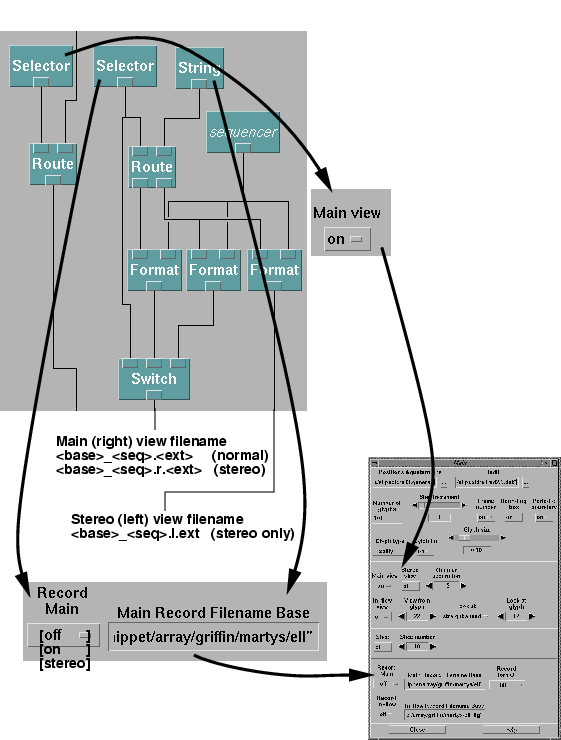
For any recording to take place, in stereo or otherwise, the Main View
must be set to On. This will dynamically activate the Image module(s) that
will save the images to disk files.
The user supplies a filename base. This can be anything the user wants. If the user has set Main Record to Off, the filename is ignored and no image files are generated. If it is set to On, we add a sequence or frame number and a suffix based on the output file type the user has chosen. The sequence number is incremented when a new image is generated. With Main Record set to On, we are not recording a stereo movie. This filename is passed on to the Image module for the Main (right) view. If Main Record is set to Stereo, then two thing happen. First we add a ".r" (for "right") just before the extension to the Main (right) view filename. Second, we create and second filename with a ".l" (for "left") just before the extension, instead of ".r." This filename is NOT created unless Main Record is set to Stereo. The left filename is passed to the Image module for the left view. The suffix is the same for both files (that is the file types are the same).
The Record Enable flag for the right view must be on when Record Main
is set to either On or Stereo. The Record Enable flag for the left view
must be on only when Record Main is set to Stereo. Otherwise it
must be off. In either case recording only takes place if the Main View
is set to On.
With such an ordering, a utility such as ilstereoview can easily be used to view the movie in full stereo using the Crystal Eyes system. Contact Steve Satterfield at NIST Gaithersburg, 301-975-5637 for more information about ilstereoview.