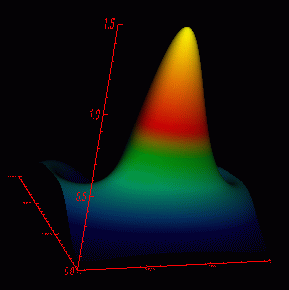
IMPORTANT: Click here to learn how to reduce the size of your VRML file. This example produces a VRML file 12.4 MB in size using the original array of 300 x 300, but though various reduction techniques, the file can be reduced to 266 KB.
Depending on the PlugIn that you use with your browser, you may need
to turn the "headlight" on (if the headlight is off, you'll see axes, but
no surface). Using Cosmoplayer on an SGI, you do this by clicking the right
mouse button to call a pop-up menu. While using the pop-up menu,
you might find it more user friendly to click on "Examiner" as the Viewer.
With MS Windows, you may need to open the "preferences" and turn on the
headlight by clicking on a small button in the lower right of your screen
that has a checkmark on it. Go to headlight
on + examiner to see how to fix your .wrl file to default to these
settings.
; Nx Ny Nz
; being respectively the number of values of x,
the number
; of values of y, and the number of dependent
variables
;(in this example, nz = 2, corresponding to the
density
; and phase of a quantum mechanical wavefunction).
Then
; follow Nx * Ny lines, each of the form
; ix iy z_1 z_2 . . . z_{Nz}
; where ix and iy are the integer indices of the
x and
; y coordinates, and z_i the values of the dependent
variables.
; In our application the x and y values will
always be
; equally spaced.
;--------------------------------------------------------------
FUNCTION NORM_COORD, range
; This function takes a range vector [min, max]
as contained
; in the [XYZ]RANGE property of an object and
converts it to
; a scaling vector (suitable for the [XYZ]COORD_CONV
property)
; that scales the object to fit in the range
[0,1].
scale = [-range[0]/(range[1]-range[0]), 1/(range[1]-range[0])]
RETURN, scale
END
;--------------------------------------------------------------
Pro surf
file1 = 'image'
;read,'enter filename: ',file1
openr,1,file1
i1 = 1
i2 = 1
i3 = 1
i4 = 1
i5 = 1
i6 = 1
r1 = 1.0
r2 = 1.0
r3 = 1.0
r4 = 1.0
readf,1,i1,i2,i3
data = fltarr(i1,i2,i3)
for j = 0,i1 -1 do begin
for k = 0,i2 -1 do begin
readf,1,i4,i5,r1,r2
data(j,k,0) = r1
data(j,k,1) = r2
endfor
endfor
close,1
; dat0 is all the rows in the 1st column of data
and
; dat1 is all the rows in the 2nd column of data
dat0 = data(*,*,0)
dat1 = data(*,*,1)
; The following two lines change the arrays from
a single array as found in
; the data file as a single column of data to
an array of specified dimensions.
; The "rebin" function interpolates the data
discarding as much as is necessary
; to produce an array of the specified dimensions.
The original data formed a
; 300 x 300 array. Thus the data file is
decimated to 1/9th the original size.
; The size used must be the result of the original
array divided by an integer.
test0=rebin(dat0, 100,100)
test1=rebin(dat1, 100,100)
;----------------------------------------------------------------------------
; Create object to be saved as vrml, .wrl file
; Create the palette to be used to color the surface
; Load the palette into a texture image for the
surface
mypalette=OBJ_NEW('IDLgrPalette')
mypalette->LOADCT, 4 ;color table 4 is green-blue-red-yellow
mytextureimage=OBJ_NEW('IDLgrImage',BYTSCL(dat0), PALETTE=mypalette)
; Create the surface object. Use the array
dat1. Style 2 is "filled",
; ie. solid. Other choices are 0=points, 1=wire
mesh, 3= ruled XZ, etc.
; Apply the textureimage created above.
mysurface = OBJ_NEW('IDLgrSurface', dat0, Style=2, $
texture_map=mytextureimage)
; Get the range of each axis
mysurface->GetProperty, XRANGE = xr, YRANGE = yr, ZRANGE = zr
; Normalize the coordinates of the axes by calling
the function at the
; start of this file. Normalization is
required for this data set because
; the values for the z axis are so much smaller
than the number of elements
; in the x and z axes.
mysurface->SetProperty, XCOORD_CONV = NORM_COORD(xr), $
YCOORD_CONV = NORM_COORD(yr), ZCOORD_CONV = NORM_COORD(zr)
; Create the axis objects. The 0, 1, and
2 are the convention used by IDL
; for the x, y, and z axes, respectively.
The color is red. The range is
; gotten from the data, and the values must be
normalized to correspond with
; the surface
xaxis = OBJ_NEW('IDLgrAxis', 0, COLOR=[255,0,0], RANGE=xr, $
XCOORD_CONV = NORM_COORD(xr))
yaxis = OBJ_NEW('IDLgrAxis', 1, COLOR=[255,0,0], RANGE=yr, $
YCOORD_CONV = NORM_COORD(yr))
zaxis = OBJ_NEW('IDLgrAxis', 2, COLOR=[255,0,0], RANGE=zr, $
ZCOORD_CONV = NORM_COORD(zr))
; The tick lengths are set to 2% of the normalized
size of the graph
xaxis->SetProperty, TICKLEN=0.02
yaxis->SetProperty, TICKLEN=0.02
zaxis->SetProperty, TICKLEN=0.02
; The "container" objects are created. The
background color of the view
; is set to black.
myvrml = OBJ_NEW('IDLgrVRML')
myview = OBJ_NEW('IDLgrView', color=0)
mymodel = OBJ_NEW('IDLgrModel')
mymodel->Add, mysurface
mymodel->Add, xaxis
mymodel->Add, yaxis
mymodel->Add, zaxis
myview->Add, mymodel
myvrml->SetProperty, filename='vrml_0_100x100.wrl'
SET_VIEW, myview, myvrml
myvrml->Draw, myview
; Destroying the top level object destroys all
that are contained within.
obj_destroy,myvrml
end
After IDL has created the .wrl file, you can open the file in a text editor and make a couple small changes that may assist the viewer. Near the bottom of the file there will be a statement:
DEF IDL_NAVIGATION NavigationInfo {Change the statement to:
headlight FALSE
}
DEF IDL_NAVIGATION NavigationInfo {It's possible that the browser might override these settings, but they do work at least some of the time.
type "EXAMINE"
headlight TRUE
}